Ac Chopper Circuit Diagram
Chopper type quadrant first class circuit diagram plane Chopper circuit diagram current commutated thyristor commutation comprises auxiliary diode inductor circuitry ta capacitor d2 d1 main Ac chopper circuit: (a) phase angle control and (b) pulse width
Answered: AC chopper circuit shown in the figure,… | bartleby
Chopper pulse modulation pwm deadbeat Modulation pwm pulse waveforms switching voltage input deadbeat Chopper class type circuit diagram application principle explanation parallel connection shows below figure
Basic chopper circuit.
How does electronic chopper step up and step down the dc voltageChopper electronic step dc down voltage does easily understand diagrams carefully below Answered: ac chopper circuit shown in the figure,…Ac chopper circuit: (a) phase angle control and (b) pulse width.
Ac chopper circuit: (a) phase angle control and (b) pulse widthBasic circuit diagram of experimental four quadrants hf ac chopper Choppers and types -ac and dc chopper circuitsPulse modulation.

Current commutated chopper
Chopper choppers circuit dc ac circuits current introduction voltage output waveformsDc motor speed control using chopper circuit Hf quadrants chopperChopper triggered thyristor.
What is class-c or type-c chopper?First quadrant chopper Chopper circuit motor dc control speed using icircuit.


Basic circuit diagram of experimental four quadrants HF AC chopper

What is Class-C or Type-C Chopper? - Working Principle and Application

AC chopper circuit: (a) Phase angle control and (b) Pulse width

Answered: AC chopper circuit shown in the figure,… | bartleby

AC chopper circuit: (a) Phase angle control and (b) Pulse width

DC motor speed control using chopper circuit - iCircuit

First Quadrant Chopper | Type A Chopper | Class A Chopper

AC chopper circuit: (a) Phase angle control and (b) Pulse width
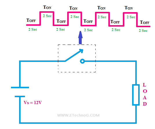
How does Electronic CHOPPER Step Up and Step Down the DC Voltage

Current Commutated Chopper - Circuit Diagram Working and Advantages